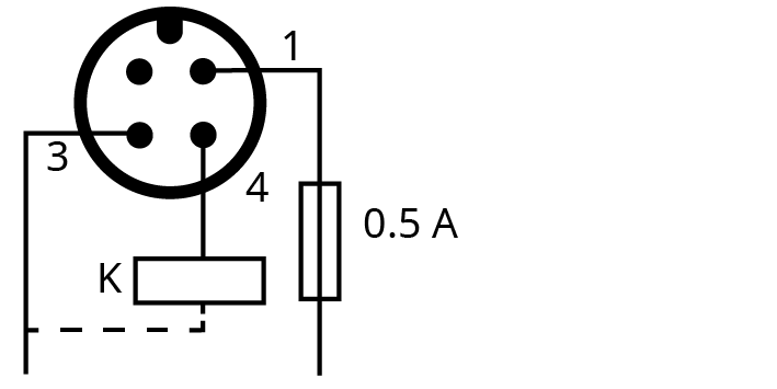
Wiring Diagram Level Switch (Optional)
Part no.: 0652 567 576
Connector: M12x1, 4-pin
Electrical data: U = 10 – 30 V DC; I consumption: <15 mA; I output max: 150 mA
Switch point: Pin 1 = low level

1 = Brown: Supply +24V DC; 3 = Blue: Supply 0V DC; 4 = Black: Signal low level
NOTE: For this device, the recommended time delay to prevent nuisance alarms can be up to 240 seconds.